Thursday, April 30, 2020

High Efficiency Table Saw Dust Hood


I know a lot of shops fight the same constant battle that I do against dust.  One of the biggest offenders in my shop is the table saw.  This tool is used extensively every single day and as much as I like the table saw I have, the factory dust collection ports seem to be a bit of an afterthought in the design and leave a lot to be desired.  Most moderately priced table saws I have owned and considered purchasing seem to have similar shortcomings in dust collection.  My saw, in particular, has a plastic hood that rides over top of the riving knife that is supposed to keep dust from flying up and redirect it to the dust port under the blade.  However, due to the open clearance needed for the tilt mechanism, it is wide open underneath and half the dust makes it into the dust collector basically by chance and the rest ends up in the air or on the floor.  To make matters worse, it is only a 2 ½” port.

The solution I came up with is designed to extract a very high level of dust with rip cuts under 3” wide and 1” thick.  In my shop, the vast majority of cuts are rips under 3” in ¾” material so it will not work well for cutting large plywood panels, wide boards, crosscuts or thick material.  However, the hood is attached to the rip fence and simply slides out of the way, usually without having to be removed.  The factory hood is simply tilted back down over the blade.  If the hood does need to be removed it is a simple matter of loosening 2 threaded knobs.  My saw is set up with a 2” wide x 3” tall rip fence with a 1 ½” x 1 ½” l shape rider made of ¾” plywood and a 1/8” angle aluminum face.  The dimensions given are built around this so you may need to modify as necessary to fit your machine or needs.

Using the new hood has been a tremendous difference.  With the factory set up I estimate 50% of the dust was being collected.  With the new hood, I estimate conservatively 90% of the dust is being collected.  There is a noticeable difference in the entire shop.

Far and away the most intricate part of the build is the clear acrylic face.  The main face part and two tilting blade covers were cut from a single 18” x 24” sheet of ¼” thick acrylic.  (fig 1)  I made 2 of the tilting blade covers simply to have a spare because I can see this part potentially wearing out or getting damaged over time.  The parts were cut with a CNC router set to a high travel speed and low RPM.  However, this can certainly be cut with more traditional tools like a jig saw and a drill.  I have attached a scalable drawing.  (fig 2)  I will also be happy to share the V-carve CAD drawing and .tap toolpath file.  Just send me an email or ask in the comments section. 


The acrylic needed to be bent at a 90ׄ° angle.   It could also be glued together as 2 pieces but I prefer the cleaner method of bending the acrylic.  (fig 3 & 4)  I used a shop built acrylic bending jig.  There are many tutorials on how to easily build one of these with a piece of resistance wire. 


The wood pieces that need to be cut are fairly straightforward.  I used ¾” red oak, but only because that is what I happen to have lying around.  Any ¾” hardwood will work fine.  (fig 5)   Below is the list of finished material:

Top Board – 6” wide x 11 ¾” tall.  Both sides cut on a 20° angle parallel to each other

Base board – 2” wide x 13” long

Back support – 2” wide x 2 ¼” long.  One side cut on a 20° angle so the 2 ¼” side is the short side

Filler Post – 1” wide x 2 ¾” long.  Cut across the 1” side at 20° angle so the 2 ¾” side is the short side.

Front connector – 2” wide section of 1 ½”x1 ½” right angle aluminum.  I cut one of the legs down to 1” purely for aesthetics.  It is not necessary.  Drill 2 holes matching the two holes in the acrylic directly below the 4” hole.

With the basic pieces cut there is one other component that needs to be addressed before assembly begins.  The acrylic blade flap (fig 6) will be held down with a thumb screw which will need a stable set of threads to screw into.  To accommodate this, a 1” x 4” piece of the ¾” oak stock was used to provide a base for a threaded insert.  (fig 7)  After drilling and placing the threaded insert it was bolted to the bottom of the Top board out of the way of the blade.  (fig 8).


Assembly of the basic structure starts with attaching the top board to the acrylic face with #6 x ¾” wood screws making sure the head of the screw is below the surface of the acrylic allowing the blade flap to rotate upward without obstruction. (fig 9) 

The back support will need to be attached to the base board 2” from the end of the board with #6 1 ½” screws.  This allows enough room on the base board for the rear mounting bolt and threaded knob.  Then the base board assembly is attached to the acrylic face with #6 1 ½” screws in the back and #10 1 ¼” in the front making sure to place the right angle aluminum in front of the acrylic plate  (fig 10)

The filler strip is then attached alongside the back support with #6 1 ½” screws.  (fig 11)

The next step is to attach the dust port to the acrylic face.  I used a round 4” flanged dust port found at any woodworking supply store.  Hold the port in place and using the mounting holes in the dust port as a template drill through the acrylic.  Using ¾” long machine screws with washers, lock washers and nuts, attach the dust port to the acrylic face.  (fig 12)

To make the port channel on the fence side of the hood I elected to use a 20” slice of 14” wide light gauge galvanized metal roof flashing because it has about the right balance between malleability and rigidity.  There needs to be a crease on about a 20° angle near one side.  Using a sheet metal brake, I found it advantageous to crease it along the natural curl of the metal from the roll.  (fig 13)  This light sheet metal can also be creased by clamping 2 scrap boards together to sandwich the metal and then pressing the seam with a third board.

Using a pair of pliers, sheet metal pliers are ideal, flatten the crease back out of one end of the metal perpendicular to the seam at least an inch from the edge. (fig 14)

Mounting the sheet metal to the hood requires using some form of clamping strip.  I used ¾”x1” strips of wood, but metal or aluminum bar stock would work well too.  The lengths are 11 ¼” for the bottom, 11 7/8” for the top and 2 ¼” for the side cut on a 20° angle. (fig 15)

Place the sheet metal on the fence side of the hood so the crease in the metal meets the angle in the acrylic face below the dust port.  Secure it with a few screws allowing the metal to extend beyond the edges of the hood.  (fig 16)

Form the metal into a cone shape and mark where it meets the edges of the dust hood.  (fig 17 & 18)


Once the metal has been trimmed with a pair of tin snips or shears and the edges filed, attach it to the dust hood using the clamping strips. (fig 19 & 20)  A little silicone sealer along the edges of the metal and any other gaps will make a difference.


Attach the blade flap with a ¼” x 1” bolt secured with a lock nut through the front hole and a ¼” x 1” thumb screw in the rear hole tightening into the threaded insert.  (fig 21)

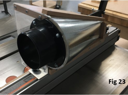
To mount the hood on the fence, it was placed on the fence and marked for ¼” thumb screws.  Once drilled, t-bolts were placed in the fence and tightened with threaded knobs.  (fig 22 & 23)


A “Y” connector is used to split the dust collection between the factory port at the bottom and the new port on the dust collection hood.  (fig 24 & 25)


The blade flap can be tilted up and out of the way to slide the fence by loosening the thumb screw.  (fig 26)

Here is a video link


Rod Gunter is Operations Manager at Gunter Building Solutions and has over 20 years of experience in the homebuilding and cabinetry industries.  Rod has been responsible for building over 200 homes above the $500,000 price point.  Rod has trained large groups including all the major home centers on selling skills, construction techniques and sustainable natural wood products.  Rod resides with his family in Holly Springs, North Carolina.  Gunter Building Solutions owns WoodAirGrille.com which produces wood return air filter grilles and wood return air vents.


Monday, November 25, 2019

Easy Cable Management


As I was building a desk for my son, one of the key objectives was incorporating a way to manage all those loose cords and cables.  The desk itself utilizes a vented corner cabinet to hide the power strips and transformers, but in this article, I want to focus on the raceways which can be adapted to any desk, table or wall.  The raceways themselves are very easy and inexpensive to construct.  They are highly versatile in size and are not limited to a straight line.  Then I added to “cool factor” by routing LED strips through it.


So, let’s get started.  The raceways are simply made up of vinyl tubing available at any hardware store or home improvement center.  (Fig. 1)  I focused on 2 basic styles, clear tubing and reinforced braided clear tubing.  There are multiple sizes and you will want to select the size that is appropriate for your application.  (Fig. 2)  The prices run from $1.00 to $3.00 per linear foot.  Since I wanted to accommodate a 14 gauge extension cord, LED strip, and several other smaller cords, I chose a fairly large 1” inside diameter clear vinyl tube for my project which cost $1.59 per linear foot.


Having purchased several lengths of tube to experiment with, I encountered a minor issue with some of them.  A few wanted to curl up from being packaged on a spool.  This was easily overcome and a quick internet search revealed a multitude of ways to straighten them out.  Methods included putting them in boiling water, putting them in the oven at a low temperature, setting them in the sun and so on.  I picked up a heat gun and blew it into one end of the tubing making sure I could feel the heat coming out of the other end.  Within just 3-4 minutes, I watched the tube magically uncurl itself into a near perfect straight line.  I was a bit surprised at how easy and effective it was.  I imagine you could achieve the same result with a hair dryer, though it may take a few minutes longer. 

Cut the tubing to the desired length.  (Fig. 3)  Then, using a utility knife, heavy duty scissors or tin snips, slit the length of the tubing.  (Fig. 4)


I chose to use ½” pan head sheet metal screws, to attach the tube to the bottom of the desk, (Fig. 5 & 6) but you can also use double sided tape.  (Fig. 7)  The key is to keep the attachment point near the lengthwise slit in the tube.  Therefore, the tube is forming a hook to hold the cords up.  (Fig. 8)  If you are mounting the tubes under a desk, I suggest keeping the slit toward the back so that if you want a cord to exit the tube anywhere along the run, it will remain hidden.


The cords will slip into the tubing through the slit.  The cords can run end to end or, as mentioned before, they can exit the tubing anywhere along the run.  (Fig. 9 & 10)  Notice in Fig. 10, with the flexible vinyl tubing, you are not limited to straight segments.


Now for the optional, but more fun part.  With the clear tubes, it is easy to add LED strip lights.  I ordered the “peel and stick” type.  Just cut the strips to the desired length on one of the designated cut lines.  (Fig. 11)  Then, just peel the backing off the tape and adhere them inside the tubes making sure to account for where you want to plug in your connectors to the control unit. (Fig. 12 & 13).  You may need to use splitters or additional connectors due to your layout.  The kits usually come with instructions and there are plenty of tutorials online with regards to customizing LED light strips, so, I’ll leave those details out of this article.


It really is that simple.  Just get some vinyl tubing, slit it, attach it in the desired location, put some lights in it if you want and run your cords through it.  I hope you find this solution helpful and fun.  Here are some finished pictures.


Rod Gunter is General Manager at Gunter Building Solutions and has over 20 years of experience in the homebuilding and cabinetry industries.  Rod has been responsible for building over 200 homes above the $500,000 price point.  Rod has trained large groups including all the major home centers on selling skills, construction techniques and sustainable natural wood products.  Rod resides with his family in Holly Springs, North Carolina.  Gunter Building Solutions owns WoodAirGrille.com, a leading manufacturer of wood return air filter grilles and wood return air vents.

Friday, June 21, 2019

Cardboard Cutting Machine

Cardbaord Cutting Machine for Wood Return Air Filter Grilles by WoodAirGrille
In my shop, I have a constant need to notch the protective carboard corners we use for shipping our wood return air filter grilles.  The need comes from needing to get around our filter housings and I have not found a stock one that fits this application, so we modify what is available.  This has typically been done simply with a pair of heavy duty scissors or tin snips, but it can be strenuous on the hands if you have to cut a lot of them, the notches are inconsistent which does not affect their performance, but doesn’t look as professional as I would like them to and it is very time consuming to cut them by hand.
The solution to was to create a machine that would notch the corners consistently, much like a table saw.  The operation is foot activated leaving the operators hands free to manipulate the cardboard easily, quickly and comfortably.  There are corner notchers for cardboard on the market that operate like a shear, but they are designed to simply round the corners.  I also investigated corner notchers intended for use with sheet metal, but they are expensive, heavy and I theorize, unlike metal, the cardboard would act like a very fine sandpaper wearing down the expensive blades over repetitive use.  That led me to pursue using electric scissors which do a great job of cutting cardboard, they are inexpensive, and the blades are easily replaceable.  It just requires a few modifications and a table built around it to suit the needs of what you are cutting.
In this case, the table is specifically set up for consistently notching cardboard corners and as you can see in the cover photo, is part of a larger system used in our shipping room that utilizes a manual shear to cut strips of MDF protective packing material to specific lengths, notch the cardboard corners and trim shipping labels to  the proper size.  In this article, we are going to focus on the cardboard cutting machine part of the system.  Incidentally, the table and stops could be configured and/or resized to suit your specific application and it would work equally well for most types of fabric or other soft sheet materials.
Researching cardboard cutting led me to electric scissors.  I found essentially two types.  One has an oscillating pair of blades more like a traditional pair of scissors.  The other has a rotating decagon or circular blade.  After testing both, I found the latter worked best for carboard not only because it cut faster, but it did not deflect the cut off side downward which would tend to bind against the table surface in my design.  The cost was less than $30.  (fig 1)
Fig 01 Cardboard Cutting Machine for Wood Return Air Filter Grilles by WoodAirGrille
Several modifications had to be made in order for my design to work.  As it comes from the factory, the electric scissors have 3 cut offs.  If it is plugged into the charger, no power can be delivered to the motor.  Fortunately, this one is an electrical switch and not a mechanical switch so it can be operated by cutting off power to the charger entirely.  More about that later.
The second is a safety switch on the top that must be depressed before the hand switch on the bottom will turn on the blade.  My best guess is that it is too easy to accidentally depress the large hand sized trigger and that necessitates the safety switch on top.  Since we will be removing the large trigger and operating a protected foot switch, I decided the top safety switch was unnecessary and bypassed it by removing the switch and soldering the wires together. (fig 2 & 3)
I then soldered two 5’ wires to the contacts for the main trigger.  Now when these two wires are connected, and there is no power to the charger, the cutting wheel will run.  (fig 4 & 5)
The main operating connection utilized a momentary push button switch in concert with a foot petal in order to free the hands of the operator to manipulate the cardboard.  The foot switches I found online were not terribly expensive, however, they were intended for higher voltage uses so I decided to just build one.  I started with 2 pieces of 1/8” x 2” right angle aluminum cut to 6” and 2 pieces of 1/8” x 2” aluminum bar stock cut to 5 ½”  I put the 2 pieces of right angle aluminum back to back and drilled a 3/8” hole 2 ½” from the front and 5/8” from the edge.  (fig 6)
Fig 06 Cardboard Cutting Machine for Wood Return Air Filter Grilles by WoodAirGrille
The holes are to accommodate the 3/8” threaded rod that the pedal will pivot on.  Therefore, after cleaning the metal, I clamp them to the 2” flat bars to form a square base making sure the holes are opposite each other on the vertical leg of the angle bar.  Using a propane torch and aluminum brazing rod, the base was brazed together.  (fig 7, 8 and 9)
Several more parts needed to be cut and prepped for assembly.  Since I was building a foot operated switch, I needed a pedal which I acquired with a quick stop by the auto parts store.  This clutch pedal was Ideal because It had predrilled and countersunk holes for mounting.  I simply used it as a template to cut down a piece of 1/8” aluminum bar stock and bore the matching holes.  (fig 10)
Fig 10 Cardboard Cutting Machine for Wood Return Air Filter Grilles by WoodAirGrille
After cutting a 4 ¾” piece of 1” aluminum square tubing two holes needed to be cut.  One is a 3/8” hole for the threaded rod 1 ¼” from the end, and the other is a ¼” hole drilled 3/8” from the back.   I mounted the flat stock for the pedal to it at a right angle with some self boring screws. (fig 11)  Then the pedal was mounted to the flat stock.  (fig 12)
In order to keep the pedal from wondering back and forth on the threaded rod, I cut two pieces of aluminum tubing with a 3/8” inside diameter at 2 1/8”.  (fig 13)
Fig 13 Cardboard Cutting Machine for Wood Return Air Filter Grilles by WoodAirGrille
After cutting a 3/8” threaded rod to 6 ¼” it was mounted to the base centering the pedal assembly between the 2 aluminum tubes and washers secured by some nylon insert lock nuts to allow free movement.  A 1/8” hole was drilled just to the side of the square tubing at the rear of the base to secure a small spring.  A ¼ x 1 ¾” screw was inserted through the hole previously drilled in the back of the square tubing.  The other end of the spring attaches to this and an additional nylon insert lock nut is placed at the end to prevent the spring from slipping off the assembly.  (fig 14)
Fig 14 Cardboard Cutting Machine for Wood Return Air Filter Grilles by WoodAirGrille
Using some 1/8” x 1” bar stock cut to 7”, I bent both ends to 90° at about 1 ¾”.  After drilling a 7mm hole in the middle of the bar stock I mounted the momentary switch with the button facing down in the same direction as the 90° bends.  1/8” holes were drilled ½” from each end for the mounting screws.  (fig 15)
Fig 15 Cardboard Cutting Machine for Wood Return Air Filter Grilles by WoodAIrGrille
With the aid of some vice grips to position the switch at the desired height, I drilled through the vertical leg of the base using the hole previously drilled in the bar stock as a guide.  (fig 16)  The primary reason for mounting the switch facing down and using a lever to press it as opposed to just placing it under the pedal was to allow the pedal to be closer to the ground and thus, more comfortable for the operator.  A residual benefit is that the bar stock the switch is mounted on will flex slightly reducing pressure on the momentary switch and promoting longer life.
Fig 16 Cardbaord Cutting Machine for Wood Return Air Filter Grilles by WoodAirGrille
The completed base assembly is complete.  (fig 17)  However, to minimize the chance of the switch being inadvertently activated I decided to build a shroud to shield the pedal.
Fig 17 Cardbaord Cutting Machine for Wood Return Air Filter Grilles by WoodAirGrille
The shroud is constructed of a light gauge sheet metal cut 5 ½” x 18’ and notched for the threaded rod with a nibbler.  (fig 18)  The two sides were folded 5 7/8” from the end in a sheet metal brake.  (fig 19)  A quick coat of paint (fig 20) completes the shroud.
The shroud is mounted to the base with some 1/8” x 5/8” screws and the foot switch is complete (fig 21)
Fig 21 Cardbaord Cutting Machine for Wood Return Air Filter Grilles by WoodAirGrille
With the foot switch complete, it was time to turn my attention back to mounting the scissors on the table.  The frame of the table was constructed of 2×4 with a ¾” laminated top to be mounted on the frame.  I added two ¾” x 3 ½” boards spaced 4” apart with 3/8” mounting holes dilled 5/8 from the edge and 5 ¾ from the end of the two boards.  A second pair of 5/16” holes were drilled 5” back from the 3/8” hole centers and 1 ¼” down from the edge of the board.  (fig 22)
Fig 22 Cardboard Cutting Machine for Wood Return Air Filter Grilles by WoodAirGrille
When the large trigger was removed from the scissors, two shoulder holes were left on either side where the previous trigger pivoted.  Utilizing these holes as mounting points, I used a tap to cut 3/8-24 threads approximately 3/8” deep into the scissors.  (fig 23)
Fig 23 Cardboard Cutting Machine for Wood Return Air Filter Grilles by WoodAirGrille
The scissors are mounted to the table with two 3/8-24 x 1 ¼” bolts tightened gently into the plastic holes tapped earlier.  Nuts with washers to distribute the pressure are tightened against the scissors.  The charger cable needs to be plugged into the back of the scissors before the ¼” x 6” bolt is inserted into the lanyard hole at the back of the scissors.  Nuts are again tightened against the scissors to ensure it remains stable when it is under load.  (fig 24)
Fig 24 Cardboard Cutting Machine for Wood Return Air Filter Grilles by WoodAirGrille
A hole is cut in the laminated top to accommodate the protrusion of the scissors cutting blade and it is mounted to the table.  In this particular application, an aluminum fence is mounted to the left of the blade for repetitive and consistent cuts.  (fig 25)
Fig 25 Cardbaord Cutting Machine for Wood Return Air Filter Grilles by WoodAirGrille
A little more wiring is required.  When the charger is energized, the scissors will not run.  A wall box is mounted to the back of the deck and a combination switched receptacle is wired to a generic plug in cord.  The switch is mounted so the down position turns on the receptacle on, disabling and charging the scissors.  (fig 26)  In the up position, the receptacle is off.  This is more intuitive as in the up position, the scissors are enable to run by activating the foot switch and when the switch is down, the scissors are disabled.
Fig 26 Cardbaord Cutting Machine for Wood Return Air Filter Grilles by WoodAirGrille
Finally, the main trigger wire are soldered to the momentary foot pedal button (fig 27) and the charger is plugged into the switched receptacle (fig 28).
The final result is a machine that notches our carboard corners quickly, accurately, and consistently. (fig 29)
Fig 29 Cardboard Cutting Machine for Wood Return Air Filter Grilles by WoodAirGrille


Rod Gunter is General Manager at Gunter Building Solutions and has over 20 years of experience in the homebuilding and cabinetry industries.  Rod has been responsible for building over 200 homes above the $500,000 price point.  Rod has trained large groups including all the major home centers on selling skills, construction techniques and sustainable natural wood products.  Rod resides with his family in Holly Springs, North Carolina.  Gunter Building Solutions owns WoodAirGrille.com, a leading manufacturer of wood return air filter grilles and wood return air vents.